

Have you ever wondered how the water supply gets into your home and to the taps?
Honestly it may not be something you ever thought about. When receiving a system that works “out of the box” we often take it for granted that it works as designed and is safe. Like water in leaky pipes, attackers will exploit weaknesses in places you aren’t looking or thinking about. The same thing happens when talking about network solutions for Kubernetes clusters.
An attacker’s goal is to remain undetected and operate in places where nobody looks. Attacking Kubernetes clusters by abusing their network plugin features allows an attacker to stay under-the-radar most of the time. It allows an attacker to hold their ground for longer periods of time and thus gather significant intelligence and perform hard-to-detect attacks that will lead to an eventual takeover of the Kubernetes cluster. Whether we are talking about tap water or networks, understanding how the system works is the best (and only) way to properly secure it.
In Part 1 of this blog series, I jump right into this dirty sewer. Join me and I’ll demonstrate how an attacker can take use of your network plumbing against you. We’ll walk through basic technological principles of Kubernetes network plugins, share two possible attack vectors that utilize some of the network plugins features and outline ways you can defend against these types of attacks.
TL;DR
- Network attacks make their comeback. Known attack techniques, such as ARP poisoning and DNS spoofing, utilize immature network mechanisms in Kubernetes network layout to once again disturb the peace of cybersecurity personnel.
- Common network plugins’ features open up the possibility of crossing over security barriers. It’s possible to bypass different Kubernetes cluster security controls and practices such as iptables rules (Linux firewall utility) , reduction of pod capabilities and hardening of the node operating system, through the subtle use of unique network features in Kubernetes environments.
Kubernetes Networking
The first thing to know is that networking is a central part of Kubernetes. You must deploy a Container Network Interface (CNI) based Pod network add-on so that your pods can communicate with each other.
Kubernetes networking is a huge world in and of itself, so I won’t be able to cover all of the different plugins and features, but I’ll provide representative examples in order to help you understand the concepts better.
In the section below, I will explain the common ground of these types of plugins so that we can establish a common technical language for understanding the rest of this series.
Kubernetes Network Architecture

Figure 1 – An abstraction of Kubernetes node network architecture
Connecting pods running on the same node or on different nodes is not trivial. To enable this connection there is a complete infrastructure, which relies mainly on network namespaces, Linux network devices, routing tables and overlay networks.
Figure 1 describes an abstraction of the network structure on a single node. Each pod is in a separate network namespace and there are network devices that create the link between the different pods and the root namespace. This is the layer that manages the data traffic inside and outside of the node.
The root network namespace contains several components. The first is the pod of the network plugin which runs (unlike most other pods) in the root network namespace with NET_ADMIN capabilities. This allows it to implement the various configurations on the node. Another component that is part of the Kubernetes infrastructure is the kube-proxy pod, that is responsible for the network properties, such as iptables rules, when creating a service in the cluster.
Apart from those components, there are four main Linux network devices. The veth (virtual ethernet), which I’ll explain in more detail later, and bridge components are responsible for connecting the pods to the network space of the node so that packets can pass between pods on the same node or continue to other devices to exit the node. The first device on the way out of the node will be an overlay device, which wraps the traffic that passes through it into an existing overlay network infrastructure between the nodes in the cluster. The last device is ens33, which is the main interface of the node and allows access to external components.
Network Plugins Common Key Features
Other than the architecture, it’s important to understand that there are several common key features between the various network plugins. These features will be the basis for the further research we will present about attacking k8s network plugins.
One feature that is similar for all network plugins is that each pod, unless configured otherwise, runs within a different network namespace. Pods won’t usually run in the root network namespace, which raises the question.
How can a packet cross from one network namespace to another?
The answer is that Kubernetes network plugins use a veth (virtual ethernet) device in order to create these connections.
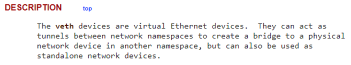
Figure 2 – Linux manual veth device description
veth devices enable connectivity between different network namespaces without exposing one container to the network characteristics of another container.
Another key device, which is present in Layer 2 network plugins, is the bridge device (br0 in Figure 1). Its main responsibility is to allow pods within the same node to talk with each other. The bridge device works like an old-school bridge, it fills its own ARP table with all the pod’s data so it would know where each packet should move to.
Last but not the least, key device is the ‘Overlay Device’. The Kubernetes network model dictates that “pods on a node can communicate with all pods on all nodes without NAT”. The alternative that allows traffic to be wrapped from many IPs without using NAT is overlay networks. It enables great flexibility with address allocations of pods in the cluster. It does this by creating an overlay network on top of the physical address of the node. This overlay network is achieved by using different tunneling protocols, such as – VXLAN, IPinIP encapsulation, etc.
As shown in figure 1, the network plugin pod is on the root network namespace. It must be there in order to do its three main jobs:
- Creating and managing network devices on the node.
- Updating and managing routing data using ARP tables, kernel routing tables, fdb (forwarding database) tables, and sometimes, running routing daemons that distribute routing updates themselves.
- Controlling the IPAM (IP address management), mainly using Kubernetes annotations, CIDRs, and local files.
The last “player” in the Kubernetes network game, is responsible for the way services are created in Kubernetes. When a service is created it is assigned a ClusterIP address that is associated with the service across the entire cluster. Behind this address, there are usually multiple pods (endpoints) with different IP addresses. You can see an example of this in figure 3.
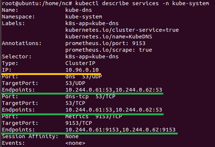
Figure 3 – Kubernetes services ClusterIP structure
The IP addresses of the pods that run the DNS service are 10.244.0.61 and 10.244.0.62 and they listen on UDP:53, TCP:53 and TCP:9153. Yet, if you send a DNS query from within a pod, you will see that the DNS server is 10.96.0.10 and that the Kubernetes service (kube-api) is on 10.96.0.1 when the true endpoint IP of kube-api is the master’s node IP (for example – 192.168.198.100).
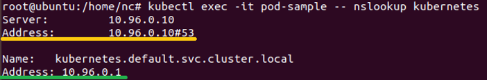
Figure 4 – Kubernetes pod DNS service ClusterIP
This mechanism is managed by the kube-proxy pod that, like the network plugin pod, runs in the root network namespace. kube-proxy (in iptables proxy mode) updates the iptables on the Kubernetes Nodes with DNAT (Destination NAT) rules that will redirect the session to one of the true IP addresses of the service’s pods.
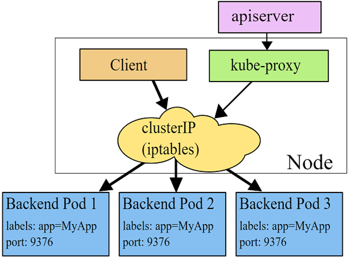
Figure 5 – kube-proxy architecture using iptables proxy mode
(source – https://kubernetes.io/docs/concepts/services-networking/service/#proxy-mode-iptables)
The Methodology of Attacking Kubernetes Cluster Trough the Network Plumbing
Now, let’s talk business.
The rest of this blog will be devoted to an introduction of two main attack vectors attackers can exploit when security best practices are not used by the different features of Kubernetes network plugins. These vectors will target the network devices that build the cluster’s network. I’ll also add specific examples of implementing those attack vectors on a widely used network plugin – Flannel.
DNS Spoofing on a Worker Node
In this section, I’ll present the first attack vector which is a way to run a DNS spoofing attack from a pod on a Kubernetes worker node. This attack vector allows an attacker to impersonate the DNS server and thus return false answers to DNS queries sent from a pod on the same worker node.
This capability allows the attacker to direct the pod’s continued communication with the desired domain to an IP address according to the attacker’s choice and desire.
This attack vector is against Layer 2 network plugins. A Layer 2 plugin means that all the pods that are on a node are on the same subnet and are not segmented by a device that blocks broadcasts on the Ethernet level.
In order to run the DNS spoofing attack, we first need to achieve a MiTM (man-in-the-middle) position. We can achieve that by using an ARP spoofing attack on the cni0 bridge device and on the targeted pod. This is a relatively simple task to accomplish because all pods that are on the same node share the same broadcast domain. In order to perform just ARP spoofing, you can use this script –
https://gist.github.com/rbn15/bc054f9a84489dbdfc35d333e3d63c87#file-arpspoofer-py
After gaining a MiTM position, a DNS spoofing attack should be pretty easy, but this is where things get interesting.
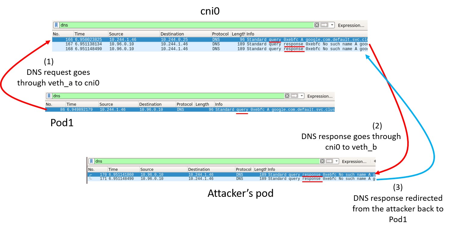
Figure 6 – DNS queries flow when running ARP spoofing attack
It would be expected that after the ARP spoofing, the DNS query would go first to the attacker. But in fact, this is what happens:
- The query never goes through the attacker.
- Only the response
- More than that – the redirected response is never received properly in the original pod.
For the attack to work properly we need to understand in more depth the process that the DNS query goes through. Once we understand this, we can understand how the attack can be carried out.
Let’s break it down.
Why didn’t the query go through the attacker’s pod first?
Remember we talked about Kubernetes services and iptables rules? This is where it all connects.
Let’s start from the basic DNS configuration file – /etc/resolv.conf
On the screenshot below you can see the DNS configuration:
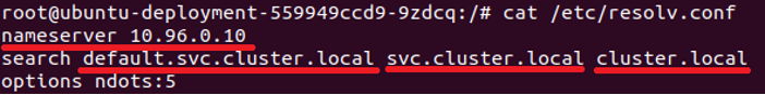
Figure 7 – Kubernetes pod’s DNS configuration file
If we look closely on the Wireshark capture in the previous figure 6, we could see that the switch of the DNS server IP address happens in the cni0 device. The IP changes from 10.244.0.25 (the real IP address of one of the DNS servers) to 10.96.0.10 due to the DNAT rules that apply to the root network namespace of the host, which was configured by kube-proxy.
When the packet goes through the cni0 device, it goes through the root network namespace, where the iptables rules take effect. DNAT rules are PREROUTING rules, which means that routing decision are taken after the destination address is changed. Because of the route changes, the packet doesn’t continue in its “original” path to the attacker’s pod.
Why did the response go back to the attacker’s pod?
Believe it or not, this is actually the expected behavior of ARP spoofing. When the packet returns to pod1, cni0 passes it to the attacker’s MAC address instead.
Why is the redirected response never received by pod1? Why is there a redirected response in the first place?
I’ll start with the second question. There is an automatically redirected response because the host is configured with IP forwarding, which applies on the pods as well. The redirected response then doesn’t get accepted as a valid answer in pod1:
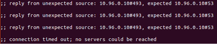
Figure 8 – Redirected DNS responses
The iptables DNAT rules expected to receive an answer from the real IP address of the DNS pod, but instead, the redirected response uses the IP address of the service (10.96.0.10) as the source IP.
Please note that even though the packet goes within the same broadcast domain, it is subject to the iptables’ rules that are contained in the root network namespace (on the cni0 device). Therefore, in order to build a packet that will meet the required criteria, the source IP shouldn’t be the IP address of the service (10.96.0.10), but the direct IP address of the DNS servers (ex. 10.244.0.25 and 10.244.0.26). In that case, the direct IP will be changed by the DNAT rule to the service’s IP address and port correctly.
All that is left to carry out this attack and spoof the DNS server is to overcome this phenomenon. In order to do so, we need to generate a response with the real IP address of the DNS pod. First, we know that we do get the response and that it doesn’t get accepted on the pod. The DNS client doesn’t care if it receives the wrong answer first, so we can issue our own afterwards. Second, we need to know the real IPs of the DNS pods. So, you could, for example, run a scan on an open UDP:53 port. Now that we have all of the information we need, we can assemble a response packet and send it. Because most of the time the DNS service will include more than a single DNS server, we will send the response from all of the DNS servers together hoping that one of them will probably catch it.
I wrote a simple POC tool that automates this attack scenario – github link
Let’s try it and see what we get.
Before spoofing:
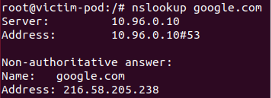
Figure 9 – Standard DNS query
After spoofing – Success:
Figure 10 – Spoofed DNS query
And as you can see, the source IP is one of the real DNS pod’s IP addresses:

Figure 11 – Wireshark capture of a spoofed DNS query
Mitigation Techniques
One main issue in these types of attack is the capability of the attacker to manipulate packets. As proposed by RedHat and Aqua, you could drop the NET_RAW capability off your application, which will prevent the attacker from using raw sockets, and thus, it will not be possible to spoof the source addresses of the packets in both ARP spoofing and DNS spoofing attacks. Most applications won’t need to use this capability. This capability is in use mostly for applications that manipulate network packets intentionally.
The second issue here is the joined broadcast domain in Layer 2 networks. In that case, you could also change to a Layer 3 network plugin (like Calico), where the pods aren’t on the same broadcast domain. This kind of solution brings other difficulties with it because it requires changes in the already existing infrastructure. If you’ve used some kind of Kubernetes operations solution, such as ‘kops’, you may have a built-in mechanism to switch between different CNI providers. Otherwise, it requires you to manually reconfigure your Kubernetes infrastructure.
Another option is to set up a firewall configuration (using iptables) that won’t allow the transfer of DNS responses (source port – UDP 53, TCP 53, or TCP 9153) from a pod that is not a DNS server to another pod.
Using the Overlay Network to Overcome Obstacles
As we saw in the previous section, we can mitigate those kinds of network attacks by dropping the capability of manipulating packets or by segmenting the broadcast domain into micro-segments.
An attacker would probably then think, “What can I do now despite the reduction of the capabilities?”
Well, there is another variable in the equation, the overlay network. This second attack vector will demonstrate how we can utilize overlay network to bypass security barriers to perform different network attacks.
An overlay network is a computer network that is layered on top of another network. Overlay networks are in a wide use of Kubernetes network plugins. Their main purpose is to differentiate the network space of the nodes from the subnet allocations of the pods, without using NAT tables.
Figure 12 – Packet structure in a Kubernetes overlay network
There are multiple ways to implement overlay networks. One of them, that is widely used, is VXLAN (Virtual Extensible LAN).
In this section I’ll demonstrate how to manipulate the features of overlay networks in order to bypass security policies such as dropping the NET_RAW capability from the pod, adding a reverse path filtering on the pod’s device, and circumventing a network firewall policy (or iptables rules).
I’ll use Flannel as the network plugin for this section’s examples as well.
Prerequisites –
- A low-privileged user on a pod
- A pod that is associated with a service account that is granted a “list” (verb) privileges on “nodes” (resource). That is needed in order to get the VTEP (Virtual Tunnel End Point) address of the VXLAN device (MAC address of flannel.1)
Note: In other implementations of the overlay network (such as using IPinIP encapsulation) you might not need these permissions, a simple IP address scan on the desired subnet would work as well.
Source IP Spoofing
Example of an attack scenario: We (as the attacker) are running malicious code on a web server running on a pod. We aim to run a SYN flood DoS attack on the DB server, but,
- The firewall policy dictates that only the back-end server can send packets to the DB server, so we have to spoof the back-end server’s IP address.
- The pod of the webserver is dropped off the NET_RAW capability, so we can’t just spoof the source IP address.
Understanding the structure of a packet going through an overlay network will give us an idea of how this can be used to our advantage.
To parse Flannel’s VXLAN packets in Wireshark, you can use this Lua script I adjusted –
https://github.com/C-h4ck-0/Flannel-VXLAN-Wireshark-parser
Figure 13 – Flannel VXLAN packet structure
VXLAN is an encapsulated packet within a UDP packet, so we can also look at it as:
Figure 14 – Unparsed Flannel VXLAN packet structure
The key points from this angle include:
- Even a low-privileged user can send UDP packets to port 8472 and, of course, he can choose what would be the payload
- The source IP address of the VXLAN packet doesn’t matter. Only the destination VTEP MAC address is verified, and that’s one part of the user-controlled payload in the packet
That’s why we can send something like this as a UDP payload:
Figure 15 – VXLAN packet as a structured UDP packet
Only pod-to-pod communication is being encapsulated, which is why we choose to set the IP destination as the node’s IP address. This way, it won’t go through flannel.1 device and won’t get double tagged as a VXLAN packet.
The receiving device can’t tell that the packet didn’t really pass through flannel.1 device because we “tagged” the packet as VXLAN. The received packet is handled just like any other packet would be:
- A packet with UDP destination port 8472 is sent to flannel.1 device (only the chunk of VXLAN-Data, without the headers)
- 1 device checks for the validity of the VTEP destination address and passes the inner L3 packet to the destination IP (the DB server in the example). The VTEP source address isn’t verified
- The DB server pod receives the packet from cni0 device (source MAC address is cni0 and destination MAC address is DB server pod) and thinks it got it from the back-end-server pod
An attacker can send these kinds of spoofed source IP packets to any VTEP device on any node of the cluster. It depends, of course, if he knows the VTEP’s MAC address.
Let’s try it on this architecture:
Figure 16 – Kubernetes architecture that demonstrate the use of a layer 2 overlay device
Note: In order to simplify things, the added iptables rule isn’t the whitelist best practice.
As you can see in figure 17, a packet from the web server directed to the DB server won’t pass through. This packet capture is taken from the flannel.1 device. It’s important to note that if we would take a capture from cni0 it would be empty because the packet is dropped.
Figure 17 – Flannel.1 device Wireshark capture of a dropped packet due to the added iptables rule
As explained earlier, all we need to do is build a legitimate TCP packet directed to the DB server on port 1433 as the payload of the encapsulated packet.

Figure 18 – A build of a manipulated TCP/SYN packet using Scapy
We assume that we have no capabilities to use tools like – Scapy or Netcat, on the webserver. So, what do you think about living off the land? With the help of bash We can use the raw packet we built in figure 18 and send it this way:
low-priv-attacker@webserver:~$ echo -ne "\x08\x00\x00\x00\x00\x00\x01\x00\x3A\xE3\xE2\x0B\x07\x0A\x11\x22\x33\x44\x55\x66\x08\x00\x45\x00\x00\x3C\x00\x01\x40\x00\x40\x06\x1F\xF2\x0A\xF4\x01\xD4\x0A\xF4\x03\x0E\xD4\x31\x05\x99\x00\x00\x04\x57\x00\x00\x00\x00\xA0\x02\xFD\x5C\x1A\x95\x00\x00\x02\x04\x05\x82\x04\x02\x08\x0A\x5E\xCA\xD8\x8A\x00\x00\x00\x00\x01\x03\x03\x07" > /tmp/send_pkt.txt
low-priv-attacker@webserver:~$ exec 3<>/dev/udp/192.168.198.148/8472
low-priv-attacker@webserver:~$ cat /tmp/send_pkt.txt >&3
We can see that the packet was received by the DB server and it responded with a “SYN/ACK” to the back-end server:

Figure 19 – A Wireshark capture showing that a manipulated SYN packet can pass through iptables rules
Now, all that’s left for the attacker to do is to send a massive amount of these packets (with different source ports), in order to SYN flood the DB server.
In this section, we’ve managed to bypass the iptables network policy and maneuver around the dropped NET_RAW capability to manipulate packets within the cluster.
This overlay network utilization method may vary depending on the different techniques used to build the network, but the concept remains the same – the content of the packets (the payload) is controlled by the attacker. This means that the attacker controls the encapsulated packet.
Mitigation Techniques
In order to perform mitigation techniques, we must first understand that each overlay network has its own unique characteristics. In this case, it’s the use of VXLAN protocol that within this specific product (Flannel) the communication is based on the UDP port 8472 of the host server. The weakness here is the ability to access this port on the server from a pod. Therefore, an iptable rule that blocks a pod from sending any packet that is destined to a cluster node’s UDP port 8472, would eradicate the risk. When dealing with the different protocols overlay networks are based on, it’s necessary to block this sensitive access between the pod and the open interface on the host server. For example, if an IPinIP protocol is used, you can block the use of this protocol between the pod and the nodes in the cluster.
The second mitigation, which as we saw is relevant for Flannel, would be to pay attention to the “list nodes” privileges you have on your cluster. It would be much more difficult for an attacker to send these kinds of packets without knowing the MAC address of the relevant VTEP. There are permissions that may be perceived as safe as they do not have the ability to make changes to the system configuration, but only have the ability to view settings. However, these types of permissions are great for reconnaissance, and it is critical to emphasize the importance of permissions and privileges that on the surface may not pose any risk. You need to have a critical eye and thoroughly understand the capabilities some of these sensitive permissions provide.
sum += 1337
While the top priority of Kubernetes operators is to provide high availability and seamless communication between the various applications, it is important to also emphasize the security features and risks of the network.
As presented, an attacker can take advantage of the different features of the network plugin in an improperly configured and secured Kubernetes deployments to execute attacks within the cluster space and bypass various mitigation methods.
New and emerging DevOps technologies bring new challenges with them. In this case, those challenges arise around a new layer of network that enables the connection between the containers and the host server. The architecture is similar. A server connected to a switch connected to a firewall is not fundamentally different from a container connected to a bridge device for which iptables rules apply. However, the realization characteristics are slightly different and therefore require security adjustments.
Hopefully, the examples and attack implementations we discussed will make it easier to understand, detect and defend against possible attack vectors that an attacker can implement as derived from the properties of the network plugin in use.
In the second part of this blog post, which we’ll publish in a few weeks, we’ll cover an attack vector that target the routing features of network plugins. We’ll reveal a new security issue that we detected in the BGP protocol, and specifically, show how you can abuse routing protocols in Kubernetes environments with an example using the Calico network plugin.
Let us know what you think and ask question in the CyberArk Commons forum https://discuss.cyberarkcommons.org/c/CyberArk-Labs/17


