

The LoRaWAN protocol wirelessly connects battery-powered devices to the internet. Because of its ability to communicate long-range with little battery consumption, it is likely to be the network of smart cities and industries in the future. High profile use cases like these require high security standards and LoRaWAN’s design is built with security at its core. In this research, we’ll share some basic knowledge about LoRa and the LoRaWAN protocol and dive into our discovery of a security issue involving a denial of service (DoS) on this protocol.
LoRa and LoRaWAN
LoRa (Long Range) is a low-frequency modulation technique developed by Semtech. The aim of this technology is to achieve long-range communication between devices together with low battery consumption. Both of these goals are achieved by using a low frequency (< 1GHz). As we can see in the following figure, WiFi and cellular networks use a higher bandwidth than LoRa, and thus have a lower range and higher battery consumption.
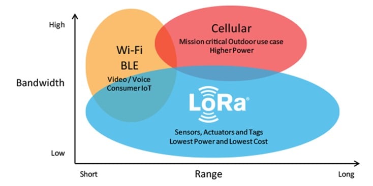
Figure 1 – LoRa vs WiFi and Cellular (Source: LoRa Academy)
LoRa communications have an impressive range of up to 15km.
On top of the LoRa technology, the LoRa Alliance has developed an open-source protocol called LoRaWAN. This protocol aims to securely connect the LoRa devices to the internet. The goal is to have battery-powered devices be able to communicate with the internet while optimizing battery life.
As such, the LoRaWAN protocol offers 3 device classes which allow adapting the battery usage to the use cases.
Device Classes
Class A: Class A devices are meant to have the longest battery life. These devices are sleeping most of the time, and thus, do not listen regularly to the network. They can receive a message from the network (called downlink) only as a response to a message they have just sent (called uplink). Basically, a Class A device will send a message, wait for a few seconds, then listen to the network for some time, and finally go back to sleep mode. Class A devices are mostly used for detection i.e. the device detects something, sends it to the internet, receives a response (in case there is something to do), and goes back to sleep until the next detection. Examples of Class A devices would be fire alarms, flood detectors, intrusion detectors, etc. (more info here)
Class B: Class B devices are a compromise between Class A and Class C. Class B devices listen to the network periodically, meaning the network can initiate the communication. A Class B device would typically listen to the network every 32 seconds (but this is configurable) which allows the application to communicate with the device on a regular basis without waiting for an uplink. Class B devices are mainly used for metering like temperature and moisture. Instead of requiring the device to send uplinks on a regular basis (which is highly power consuming), the device sends the data only when it is asked, with a few seconds of latency. (more info here)
Class C: Class C devices are continuously listening to the network except when they are sending uplinks. This type of device is the most power-consuming but offers the lowest latency. These devices are used for monitoring like traffic and water systems (more info here).
Next, we’ll look at how the protocol works. The LoRaWAN protocol is based on 4 components: Gateways, Network Servers, Application Servers and Join Servers.
The LoRaWAN Protocol
When a LoRa device wants to send a frame/packet via the internet, it will send it using the LoRa technology, in all directions.
Then, one or several Gateways will receive this packet. The Gateways are small computers (typically Raspberry Pis) that are connected to the internet and have an antenna capable of receiving LoRa packets. The Gateways simply demodulates the LoRa packets and forwards them to the Network Server via the internet.
The Network Server is like the router of the LoRaWAN protocol. The frame sent by the device contains clear text headers, an encrypted payload and a signature. The Network Server will check the signature and determine the target Application Server based on the headers. This process will allow the Network Server to forward the message to the right Application Server in case the message is correctly signed.
The Application Server is responsible for the application layer of the protocol. It receives the frames from the Network Server, decrypts them, processes the data and eventually sends responses.
Finally, the Join Server is the one responsible for security. It generates security keys for encrypting and signing the messages. These keys are securely forwarded to the devices and servers via the Network Server.
The first time a device is turned on, it starts a Join Procedure in which it will securely exchange several keys with the Join Server for encryption and signature. Note: we won’t cover the Join Procedure in this article, so we are assuming that all messages are sent after a successful Join Procedure. After joining, all the uplinks are encrypted and signed by the device using several keys, and all the downlink are encrypted and signed by the Application Server.
Now that we know the different components and devices that take part in the LoRa protocol, and how they interact with each other, let’s look closer at the communication protocol between the Gateways and the Network Server and its implementation.
Gateway to Network Server Communication – MQTT
As mentioned earlier, the Gateway is operating on the physical layer. It demodulates the LoRa uplinks sent by the devices and forwards them to the Network Server. It also receives downlinks from the Network Server (the downlinks were initially sent by the Application Server to the Network Server), modulates them and sends them to the device.
The task of the Gateway is pretty simple and limited by design. The coverage of the network is highly dependent on the number of Gateways available and therefore, the LoRaWAN protocol does not require Gateways to perform any security checks, so that their implementation is easier. This is not always the case, but, for example, TheThingsNetwork is an open-source community-based LoRaWAN network that allows any member to add a Gateway to their public network. This design requires the Gateway to be unable to decrypt the frames (confidentiality).
LoRa and MQTT
From this point, all the implementation-specific parts have been tested on a Chirpstack server infrastructure.
In many LoRaWAN implementations, the communication between the Gateways and the Network Server is achieved using the MQTT (Message Queuing Telemetry Transport) protocol. MQTT is a publish-subscribe protocol that transports messages between devices. It is designed for high-latency, unreliable networks.
The MQTT protocol consists of a server called “MQTT broker”, which collects the messages and clients that can read or write to the broker. Since it is a publish-subscribe protocol, clients should specify which topic they want to write and subscribe to (for reading). By default (without any authentication implementation), it is possible to subscribe to all the topics.
In most implementations, the MQTT broker runs on the Network Server’s machine. The Gateways listen to downlinks by subscribing to the topic: “gateway/gateway_id/command/down“ and sends uplinks on the topic: “gateway/gateway_id/event/up“. The Network server then listens to all topics with the form “gateway/+/event/up“ topics and writes downlinks to the relevant “gateway/+/command/down.”
When an uplink is sent, the Gateway writes the physical payload received from the device with additional data about it (e.g. time and frequency).

Figure 2 – MQTT Frame sent by a Gateway
We can see that the phyPayload field is encrypted. It is also signed, which prevents a malicious Gateway from modifying it without being noticed.
Uplink Signature
In order to guarantee the integrity of the uplinks, the LoRaWAN protocol requires the device to add a digital signature (Message Integrity Code – MIC) at the end of the phyPayload. The digital signature is calculated as follows:
- Calculate B0:
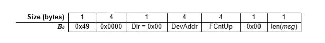
Figure 3 – B0 value for MIC calculation (Source: LoRaWAN 1.1 Specification)
Where DevAddr is the Device Address for this session, FCntUp is the uplink counter (to prevent replay attacks) and msg is the encrypted payload to be sent
- Calculate B1:
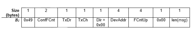
Figure 4 – B1 value for MIC calculation (Source: LoRaWAN 1.1 Specification)
Where ConfFCnt is a downlink related counter, TxDr is the data rate used for the transmission of the uplink, and TxCh is the channel (the other fields are defined like in B0).
- Calculate 2 signatures based on B0 and B1:
cmacS = aes128_cmac(SNwkSIntKey, B0 | msg)
cmacF = aes128_cmac(FNwkSIntKey, B1 | msg)
SNwkSIntKey and FNwkSIntKey are two session keys shared between the device and the Network Server (through the Join Server) that are used for integrity verification.
- Calculate the MIC (signature):
MIC = cmacS[0..1] | cmacF[0..1]
The MIC will then be added to the end of the phyPayload. When the Network Server receives the uplink, it checks the MIC before forwarding it to the Application Server. If the MIC is invalid, the Network Server will drop the uplink without forwarding it to the Application Server.
Frame Collection
As mentioned earlier, uplinks are sent over LoRa RF waves, in all directions. Thus, all the gateways in range will receive the uplink from the device. Since a gateway cannot verify that another gateway has already sent the same packet to the Network Server, this will lead to duplicates of the same physical payload on the MQTT broker (each gateway in range will write a frame with the same “phyPayload” on the MQTT broker).
For example, if 5 gateways are in the range of the device, the uplink payload will appear 5 times on the MQTT broker, with different metadata (gateway id, time, rssi, etc.).
However, on the Application Server, we want to see this message only once. Imagine a fire detection system, which would alert you 5 times for a single fire in the center of the city, and one time if it occurred in the suburb. Important information could be missed in the middle of these duplicates.
In order to address this challenge, the LoRaWAN protocol describes a message collection process, which consists of collecting all the messages that contain the same phyPayload into one single message before sending it to the Application Server.
The Security Issue: From the Attacker’s Perspective
Note: The level of trust of Gateways in the LoRaWAN protocol is not clear. While the protocol does not clearly say if Gateways should be trusted or not, some implementations assume they are not. For example, TheThingsNetwork, a global and open-source LoRa Network, relies on community-installed Gateways. In such a case, our attack would be very easy to implement.
Type of Attack: DoS on uplinks (which means full DoS on Class A devices).
Target: Chirpstack Network Server (version 3.9.0)
Prerequisite: A compromised/malicious gateway in the network. If the gateway has read/write permissions on all uplink topics on the MQTT broker, the attack can target any device in the Network. If the gateway only has write permission on the MQTT broker, the attack can only target devices in the range of the gateway.
Consequences of the Attack: In case of an alarm or detection device (e.g. fire, flood or intrusion), the device would become completely useless because the uplinks from the device would not be received by the application layer. In this case, individuals in a home, company or even a whole city may think they are safe (not receiving any alert), when they could be in considerable danger. Class A devices of any kind would become completely useless since the uplinks would not arrive, and the Application Server is only able to answer to uplinks.
Description of the Attack: In this scenario, the attacker reads a message from the MQTT broker and replays it (if s/he doesn’t have read permission, it would just need to send a payload it received from a device in range), and only changes the “frequency” field of the metadata. The 2 possible scenarios are the following:
First Scenario (The Compromised Gateway has read access to the uplink topics)
A Device sends an uplink (broadcast to all the Gateways in range)
A legitimate Gateway receives it and forwards it to the MQTT broker with the metadata. In the following message, note that the frequency is 903900000 at the end of the first line.

Figure 5 – Legitimate MQTT frame
The malicious Gateway reads this message and replays it with a single difference: the frequency field is set to 200 (not supported by the Network Server)
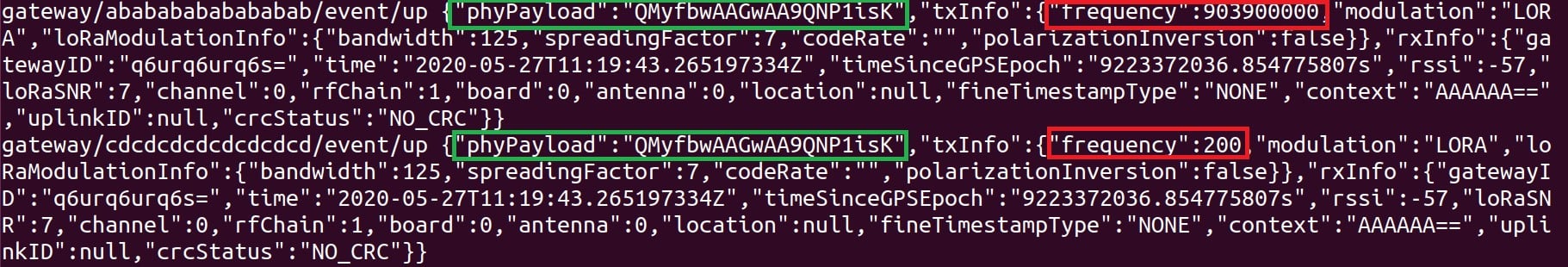
Figure 6 – Legitimate MQTT frame followed by a malicious one
The Network Server will collect those 2 messages, say that the MIC is invalid, and the uplink won’t be forwarded to the Application Server.
Second Scenario (The Compromised Gateway only has write access to the uplink topics)
A device sends an uplink (broadcast to all the Gateways in range)
The Compromised Gateway receives it and forwards it to the MQTT broker with an invalid frequency (200 for example)
Optional: Legitimate Gateways receive the uplink and forward it the right way to the MQTT broker. This does not block the attack but does reduce the chances of a successful attack.
The Network Server receives the uplinks, collects the, calculates an invalid MIC and drops the uplink without forwarding it to the Application Server.
In this scenario, the Malicious Gateway has to be in the range of the device in order to proceed with the attack.
From our comprehension of the code, and without having performed any statistical tests, we strongly believe that the probability of success increases with the number of malicious messages. A malicious gateway can thus send more malicious messages in order to increase the probability of success of the attack.
The Attack Details
The Attack Process
We first tried to perform the attack as described in the first scenario of the previous section (the malicious gateway has read access to the uplink topics). I wrote a small script which listens to all the frames that are sent to the topic gateway/abababababababab/event/up. The script would read this frame, edit the frequency to 200 and write it to gateway/cdcdcdcdcdcdcd/event/up.
import paho.mqtt.client as mqtt
import time
import re

def on_message(client, userdata, message):
    match = re.compile("frequency\":([0-9]+)")
    res = match.sub("frequency\":200", message.payload.decode("utf-8"))
    client.publish("gateway/cdcdcdcdcdcdcdcd/event/up", res)

client = mqtt.Client("FQMISLEAD")
client.connect("localhost")
client.subscribe("gateway/abababababababab/event/up")
client.on_message = on_message
client.loop_start()
time.sleep(100)
client.loop_stop()
Executing this script produces the behavior that happened in the previous section:
Figure 6 – Legitimate MQTT frame followed by a malicious one
When we performed this, the frame was not always forwarded to the Application Server. We looked at the logs of the Network Server (when the message was not forwarded) to understand this behavior:
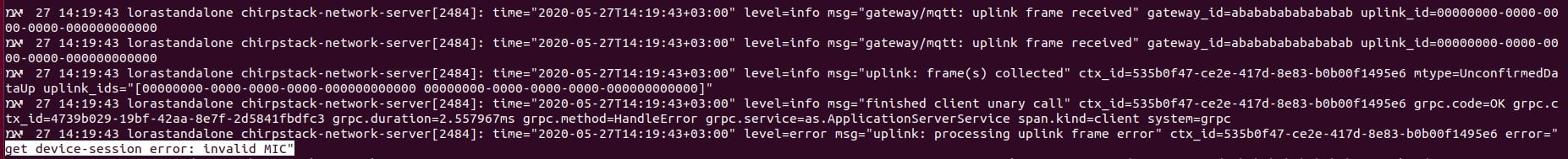
Figure 7 – Invalid MIC error on the Network Server’s logs
The error does not say that the frequency is wrong, but it says that the MIC is invalid. This sounded strange, so we decided to debug the server to better understand the error.
Debugging the Server
When the Network Server gets started, it starts listening to the MQTT broker (specifically to the gateway/+/event/up topics). Anytime a message is written in one of these topics a new thread is created:
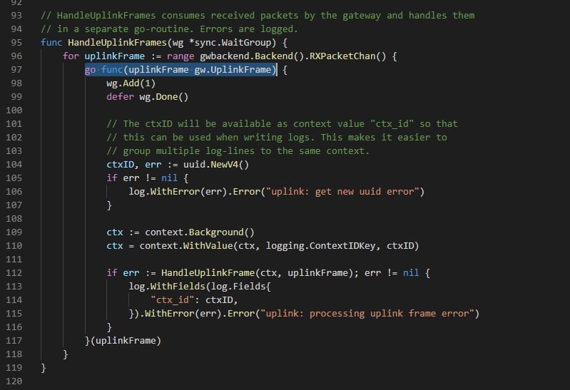
Figure 8 – New Thread created for each uplink frame (Chirpstack’s NS code – uplink.go)
This thread will wait to be collected (with the other frames – we will discuss how later), and then, the main thread will perform a series of tests and manipulations on the frame. Among those tests, the MIC is checked. When looking for the “Invalid MIC” string in the code, I saw a constant called errInvalidMIC which was referred to in the device_session.go (GetDeviceSessionsForDevAddr function) file:
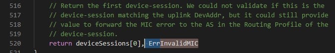
Figure 9 – InvalidMIC error being thrown in GetDeviceSessionsForDevAddr function (Chirpstack’s NS – device_session.go)
After verifying that this was the function that was causing the error, we looked for the reason why. The function declares a variable called micOK and the error is thrown if micOK is false. Here is the code which sets the value of micOK:
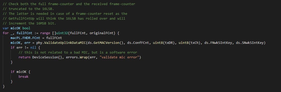
Figure 10 – micOK calculation (Chirpstack’s NS – device_session.go)
fullFCnt and originalFCnt are the different possible values for the FCnt (uplink frame counter, which is used to avoid replay attacks). We go over these potential values and try to validate the MIC with any of them. If one of is valid, we can move on with the code, otherwise we continue inside the loop. Note: the error here is only related to an internal error in the MIC verification, not to an invalid MIC value.
The validateUplinkDataMIC function computes the MIC according to its arguments and verifies if the result is the same as the one stored in phy. If they are equal, it returns true, otherwise false.
When we debugged this piece of code, we tried to send regular messages and ones with the attack to see the difference. The one major difference was that when the attack was successful, the value of txCh (Transmission Channel – 5th byte of B1 in the calculation of the MIC) passed as an argument to validateUplinkDataMIC was 0. When there was no attack or the attack was not successful, the value of txCh was 8.
We investigated to see where the value of txCh was set:
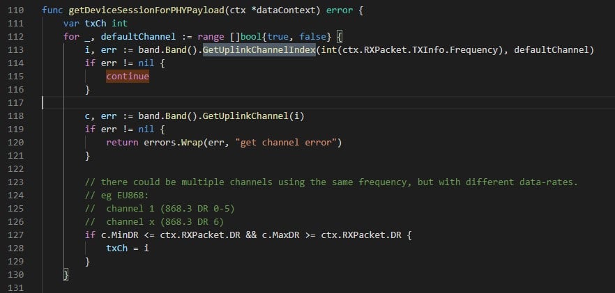
Figure 11 – Setting the value of txCh (Chirpstack’s code – data.go)
As we can see, the GetUplinkChannelIndex function allows calculating the value of txCh simply based on the frequency value provided by the gateway. When the frequency is not supported by the Network Server, the value of txCh stays the original value: 0.
Because of this invalid value for txCh, the calculated MIC is invalid, and the message is dropped by the Network Server without being forwarded.
Message Collection
In order to have a clear idea of this attack, we need to understand why the legitimate message is collected with our malicious message and why the attack fails sometimes.
As seen earlier, the collection occurs early in the processing of the uplink frame. The new thread calls several functions in cascade. The most interesting function for us is collectAndCallOnce in collect.go. It collects all the uplink frames for the same message and then calls a callback function.
The different frames are stored in a Redis Set. The key to this set is the base64 encoded string of the phyPayload field. Thus, all the frames that have the same phyPayload will be stored in the same set. The collecting function then waits for a while. When all the messages are stored in the Redis database, the collecting function sets the message’s metadata:
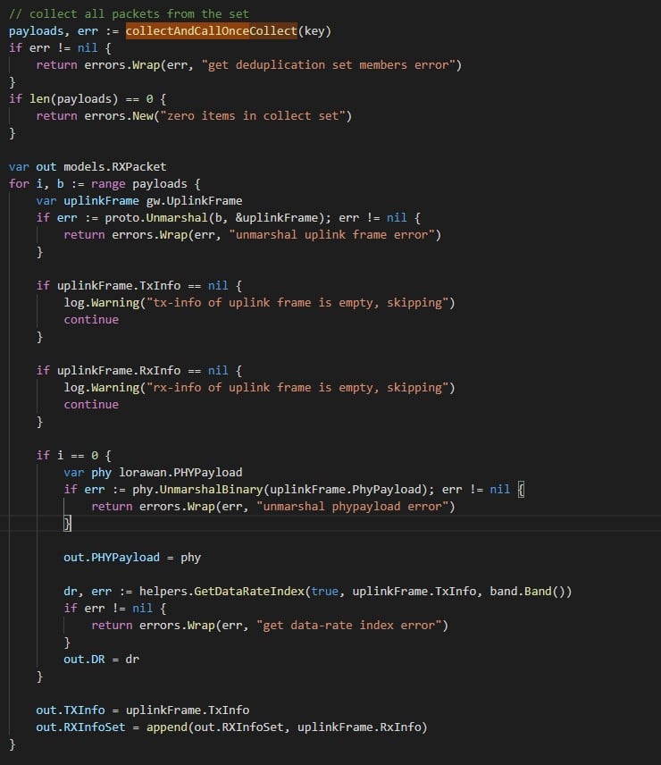
Figure 12 – Message collection after storage (Chirpstack’s NS – collect.go)
As we can see, the value of the TXInfo (containing the frequency) is set to be the frequency of the last payload in our set. Thus, our attack is successful only when the malicious message shows up after all the legitimate ones in the Redis set.
Redis sets are internally stored as Hash tables. The order of the output when we read the data out of the database is thus the order of the hashes. When we tried to perform statistical tests on Redis databases, it seemed like the hash depends on some seed stored in memory which changes occasionally. Thus, we cannot predict what the hash value would be for a specific payload.
On the other hand, since the result value of a hash can be considered random, we can assume that the probability of a successful attack can be significantly improved by sending our malicious message several times.
Responsible Disclosure
We responsibly disclosed the security issue to Chirpstack. Their team responded very quickly to our emails and fixed the issue accordingly. During our conversation, we agreed on the fact that Gateways should be trusted in order to guarantee a minimum level of security for a LoRa Network. Thus, Chirpstack’s team implemented two fixes in order to increase security and mitigate the risks associated with these kinds of issues:
- Adding the frequency to the collection key of the uplink frames. This directly targets our attack and fixes the issue in a very straightforward way.
- Not allowing unregistered gateways to communicate with the Network Server. This fix is much more general and increases the security of Chirpstack’s implementation. An attacker now requires taking over an existing Gateway in order to perform this attack. Moreover, it strengthens the consistency of the product with Chirpstack’s philosophy: Gateways should be trusted for the network to be trusted.
MQTT Security
The power of this security issue lies in an MQTT Authorization misconfiguration. With a safe configuration, the MQTT broker would block the malicious gateway from reading the uplinks of other gateways. In such a case, the attack surface would be significantly reduced and the malicious gateway would only be able to attack in its radio range — about 15km. In case of an MQTT misconfiguration, the attack can apply to the whole Network Server.
According to this article from Victor Pasknel (Morphus Labs), MQTT misconfigurations are very common on the web. In this research, they showed that more than 70% of the MQTT brokers tested (a random subset of brokers found on Shodan) do not implement Authorization at all, while 19% return “Not Authorized” and 11% return “Bad user or password” (some are likely default or weak passwords).
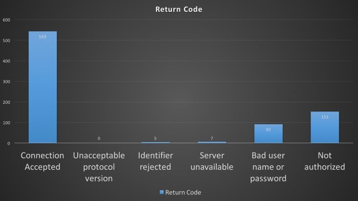
Figure 12 – MQTT Authorization Statistics (Source: Morphus Labs)
Conclusion
LoRa opens new opportunities in the world of IoT and the LoRaWAN protocol allows battery-powered devices to be securely connected to the internet for long periods of time, making it a perfect solution for modern IoT devices. Indeed, as cities and industries are increasingly adopting smart devices to better run and operate, they are putting a high level of trust in the data they provide. A denial of service attack on these devices could make the infrastructure even less secure by allowing an attacker to virtually turn off the alert systems.
It’s important to note that the implementation of protocols almost always introduce new security issues, which is why research like this is important for raising awareness. In the case of implementing MQTT broker Authorization, the procedure is well described in Chirpstack’s Documentation for the usage with a Chirpstack Network infrastructure. Although there might not be a significant security difference, we suggest configuring a different user to each gateway and highly recommend verifying the security status of each gateway in your whitelist.,
This is yet another example of the importance of a good implementation across all the elements in an infrastructure. A good implementation of the MQTT broker, in this case, would significantly decrease the attack surface of this security issue. Moreover, while protocols may be secure, the way they are implemented might present vulnerabilities, so it’s important for users to always be monitoring for any unusual behavior.


